What are Electromagnetic Flow Meters
Electromagnetic flow meters (or magmeters) are a type of velocity or volumetric flow meter that operate pursuant to Faraday’s law of electromagnetic induction – which states that a voltage will be induced when a conductor moves through a magnetic field. Magmeters can detect the flow rate of conductive fluids only. Early magmeter designs required a minimum fluidic conductivity of 1-5 microsiemens per centimeter for their operation. The newer designs have reduced that requirement a hundredfold to between 0.05 and 0.1.
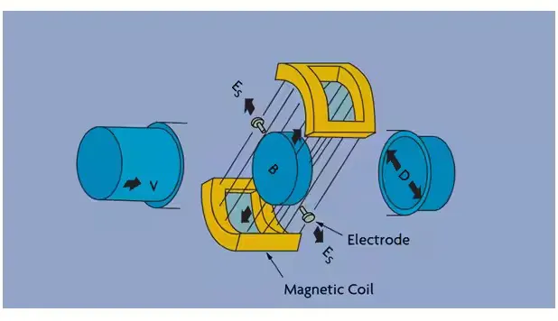
An electromagnetic flowmeter consists of a non-magnetic pipe that is lined with an insulating material. A pair of magnetic coils is situated as shown in Figure 1, and a pair of electrodes penetrates the pipe and its lining.
If a conductive fluid flows through a pipe of diameter (D) through a magnetic field density (B) generated by the coils, the amount of voltage (E) developed across the electrodes–as predicted by Faraday’s law–will be proportional to the velocity (V) of the liquid. Because the magnetic field density and the pipe diameter are fixed values, they can be combined into a calibration factor (K) and the equation reduces to:
E = KV
The velocity differences at different points of the flow profile are compensated for by a signal-weighing factor. Compensation is also provided by shaping the magnetic coils such that the magnetic flux will be greatest where the signal weighing factor is lowest, and vice versa.
Manufacturers determine each magmeter’s K factor by water calibration of each flow tube. The K value thus obtained is valid for any other conductive liquid and is linear over the entire flowmeter range. For this reason, flow tubes are usually calibrated at only one velocity. Magmeters can measure flow in both directions, as reversing direction will change the polarity but not the magnitude of the signal.
Magmeter Excitation
The voltage that develops at the electrodes is a millivolt signal. This signal is typically converted into a standard current (4-20 mA) or frequency output (0-10,000 Hz) at or near the flowtube. Intelligent magnetic transmitters with digital outputs allow direct connection to a distributed control system. Because the magmeter signal is a weak one, the lead wire should be shielded and twisted if the transmitter is remote.
The magmeter’s coils can be powered by either alternating or direct current (Figure 2). When ac excitation is used, line voltage is applied to the magnetic coils. As a result, the flow signal (at constant flow) will also look like a sine wave. The amplitude of the wave is proportional to velocity. In addition to the flow signal, noise voltages can be induced in the electrode loop. Out-of-phase noise is easily filtered, but in-phase noise requires that the flow be stopped (with the pipe full) and the transmitter output set to zero. The main problem with ac magmeter designs is that noise can vary with process conditions and frequent re-zeroing is required to maintain accuracy.
In dc excitation designs, a low frequency (7-30 Hz) dc pulse is used to excite the magnetic coils. When the coils are pulsed on (Figure 2), the transmitter reads both the flow and noise signals. In between pulses, the transmitter sees only the noise signal. Therefore, the noise can be continuously eliminated after each cycle.
This provides a stable zero and eliminates zero drift. In addition to being more accurate and able to measure lower flows, dc meters are less bulky, easier to install, use less energy, and are most cost-effective than ac meters. One new dc design uses significantly more power than the earlier generations and thereby creates a stronger flowtube signal.
Another new design uses a unique dual excitation scheme that pulses the coils at 7 Hz for zero stability and also at 70 Hz to obtain a stronger signal. Magmeter transmitters can be supplied with either ac or dc power. A two-wire, loop-powered dc magnetic flowmeter is also available in an intrinsically safe design, but its performance is reduced because of power limitations.
Pulsed ac meters have also been introduced recently, eliminating the zero stability problems of traditional ac designs. These devices contain circuitry that periodically disrupts the ac power, automatically zeroing out the effects of process noise on the output signal.
Today, dc excitation is used in about 85% of installations and ac magmeters claim the other 15% when justified by the following conditions:
- When air is entrained in large quantities in the process stream;
- When the process stream is a slurry and the solid particle sizes are not uniform and/or the solid phase is not homogeneously mixed within the liquid; or
- When the flow is pulsating at a frequency under 15 Hz.
When any of the above three conditions exist, the output of a pulsed dc meter is likely to be noisy. In some cases, one can minimize the noise problem (hold the fluctuations within 1% of setpoint) by filtering and damping the output signal. If more than 1 to 3 seconds of damping is required to eliminate the noise, it is always better to use an ac meter.
Flow tubes, Liners, and Probes
The face-to-face dimensions of flanged flow tubes (lay lengths) usually meet the recommendations of the International Organization for Standardization (ISO). The dimensions of short form magmeters usually meet these guidelines as well. Magnetic flow tubes and liners are available in many materials and are widely used in all the process industries, including food, pharmaceutical, mining, and metals.
Some liner materials (particularly PFA) can be damaged when pry bars are used while installing it or removing it from process piping. They can also be damaged by over-torquing the flange bolts. Liner protectors are available to help prevent such damage.
Any flowtube can generally be used with any transmitter offered by the same manufacturer. Depending on its construction and features, the cost of a 2-in. magnetic flowmeter can range from $1,500 to $5,000. This cost has been coming down but is still higher than that of the least expensive flow sensors.
Magnetic flowmeters also can be packaged as probes and inserted into process pipes through taps. These probes contain both the electrodes and magnetic coils. The flowing process fluid induces a voltage at the electrodes, which reflects the velocity at the probe tip and not the average fluid velocity across the pipe. These magmeters are inexpensive and retractable. Therefore, the process does not have to be shut down to install or remove them. Metering accuracy is highly dependent on the relationship between the measured velocity and the average velocity in the pipe.
Electrodes
In conventional flow tubes, the electrodes are in contact with the process fluid. They can be removable or permanent if produced by a droplet of liquid platinum as it sinters through a ceramic liner and fuses with the aluminum oxide to form a perfect seal. This design is preferred due to its low cost, its resistance to abrasion and wear, its insensitivity to nuclear radiation, and its suitability for sanitary applications because there are no cavities in which bacteria can grow. On the other hand, the ceramic tube cannot tolerate bending, tension, or sudden cooling and cannot handle oxidizing acids or hot and concentrated caustic.
In a more recent capacitively- coupled design, non-contacting electrodes are used. These designs use areas of metal sandwiched between layers of liner material. They are available in sizes under eight inches in diameter and with ceramic liners. Magmeters using these non-contacting electrodes can “read” fluids having 100 times less conductivity than required to actuate conventional flowtubes. Because the electrode is behind the liner, these designs are also better suited for severe coating applications.
Recent Developments
When a magnetic flowmeter is provided with a capacitance level sensor embedded in the liner, it can also measure the flow in partially full pipes. In this design, the magmeter electrodes are located at the bottom of the tube (at approximately 1/10 the pipe diameter) in order to remain covered by the fluid. Compensation is provided for wave action and calibration is provided for full pipe, no flow (static level), and partially filled pipe operation.
Another recent development is a magnetic flowmeter with an unlined carbon steel flowtube. In this design, the measuring electrodes mount externally to the unlined flowtube and the magnetic coils generate a field 15 times stronger than in a conventional tube. This magnetic field penetrates deep into the process fluid (not just around the electrode as with standard magmeter probes). The main advantage is low initial and replacement costs, since only the sensors need be replaced.
Choosing an Electromagnetic Flow Meter
Magnetic flowmeters can detect the flow of clean, multi-phase, dirty, corrosive, erosive, or viscous liquids and slurries as long as their conductivity exceeds the minimum required for the particular design. The expected inaccuracy and rangeability of the better designs are from 0.2-1% of rate, over a range of 10:1 to 30:1, if the flow velocity exceeds 1 ft/sec. At slower flow velocities (even below 0.1 ft/s), measurement error increases, but the readings remain repeatable.
It is important that the conductivity of the process fluid be uniform. If two fluids are mixed and the conductivity of one additive is significantly different from that of the other process fluid, it is important that they be completely intermixed before the blend reaches the magmeter. If the blend is not uniform, the output signal will be noisy. To prevent that, pockets of varying conductivity can be eliminated by installing a static mixer upstream of the magmeter.
Magmeter size is determined by capacity tables or charts published by the manufacturer. Figure 4-3 provides a flow capacity nomograph for line sizes from 0.1 in. to 96 in. For most applications, flow velocities should fall between 3 ft/sec and 15 ft/sec. For corrosive fluids, the normal velocity range should be 3-6 ft/sec. If the flowtube is continuously operated below 3 ft/sec, metering accuracy will deteriorate, while continuous operation exceeding the upper limit of the normal velocity range will shorten the life of the meter.