what is a vortex flow meter?
A vortex meter is a type of volumetric flow meter that makes use of a natural phenomenon that occurs when a liquid flows around a bluff object. Vortex flow meters operate under the vortex shedding principle, where vortices (or eddies) are shed alternately downstream of the object. The frequency of the vortex shedding is directly proportional to the velocity of the liquid flowing through the meter.
Vortex flow meters are best suited for flow measurements where the introduction of moving parts presents problems. They are available in industrial grade, brass, or all plastic construction. Sensitivity to variations in the process conditions are low and, with no moving parts, relatively low wear compared to other types of flow meters.
Vortex-Shedding History
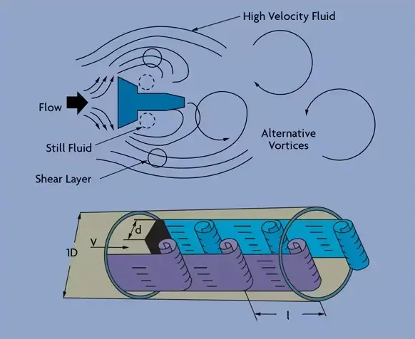
Theodor von Karman, while fishing in the mountain streams of the Transylvanian Alps, discovered that, when a non-streamlined object (also called a bluff body) is placed in the path of a fast-flowing stream, the fluid will alternately separate from the object on its two downstream sides, and, as the boundary layer becomes detached and curls back on itself, the fluid forms vortices (also called eddies or whirlpools). He also noted that the distance between the vortices was constant and depended soley on the size of the rock that formed it.
On the side of the bluff body where the vortex is being formed, the fluid velocity is higher and the pressure is lower. As the vortex moves downstream, it grows in strength and size, and eventually detaches or sheds itself. This is followed by a vortex’s being formed on the other side of the bluff body. The alternating vortices are spaced at equal distances.
The vortex-shedding phenomenon can be observed as wind is shed from a flagpole (which acts as a bluff body); this is what causes the regular rippling one sees in a flag. Vortices are also shed from bridge piers, pilings, offshore drilling platform supports, and tall buildings. The forces caused by the vortex-shedding phenomenon must be considered when designing these structures. In a closed piping system, the vortex effect is dissipated within a few pipe diameters downstream of the bluff body and causes no harm.
Vortex Flow Meter Design
A vortex flow meter is typically made of 316 stainless steel or Hastelloy and includes a bluff body, a vortex sensor assembly, and the transmitter electronics – although the latter can also be mounted remotely . They are typically available in flange sizes from ½ in. to 12 in. The installed cost of vortex meters is competitive with that of orifice meters in sizes under six inches. Wafer body meters (flangeless) have the lowest cost, while flanged meters are preferred if the process fluid is hazardous or is at a high temperature.
Bluff body shapes (square, rectangular, t-shaped, trapezoidal) and dimensions have been experimented with to achieve the desired characteristics. Testing has shown that linearity, low Reynolds number limitation, and sensitivity to velocity profile distortion vary only slightly with bluff body shape. In size, the bluff body must have a width that is a large enough fraction of the pipe diameter that the entire flow participates in the shedding. Second, the bluff body must have protruding edges on the upstream face to fix the lines of flow separation, regardless of the flow rate. Third, the bluff body length in the direction of the flow must be a certain multiple of the bluff body width.
Today, the majority of vortex meters use piezoelectric or capacitance-type sensors to detect the pressure oscillation around the bluff body. These detectors respond to the pressure oscillation with a low voltage output signal which has the same frequency as the oscillation. Such sensors are modular, inexpensive, easily replaced, and can operate over a wide range of temperature ranges – from cryogenic liquids to superheated steam. Sensors can be located inside the meter body or outside. Wetted sensors are stressed directly by the vortex pressure fluctuations and are enclosed in hardened cases to withstand corrosion and erosion effects.
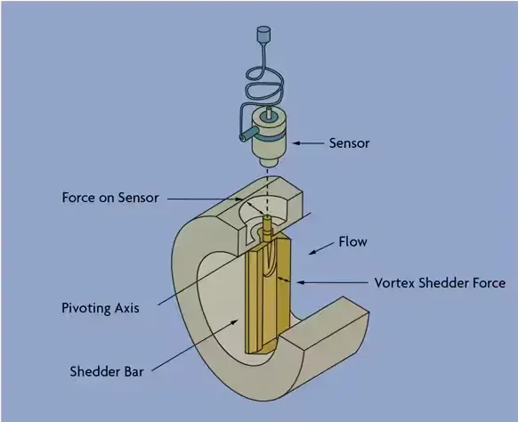
External sensors, typically piezoelectric strain gages, sense the vortex shedding indirectly through the force exerted on the shedder bar. External sensors are preferred on highly erosive/corrosive applications to reduce maintenance costs, while internal sensors provide better rangeability (better flow sensitivity). They are also less sensitive to pipe vibrations. The electronics housing is usually rated explosion and weatherproof, and contains the electronic transmitter module, termination connections, and optionally a flow-rate indicator and/or totalizer.
Vortex Flow Meter Styles
Smart vortex meters provide a digital output signal containing more information than just flow rate. The microprocessor in the flowmeter can automatically correct for insufficient straight pipe conditions, for differences between the bore diameter and that of the mating pipe, for thermal expansion of the bluff body, and for K-factor changes when the Reynolds number drops below 10,000.
Intelligent transmitters are also provided with diagnostic subroutines to signal component or other failures. Smart transmitters can initiate testing routines to identify problems with both the meter and with the application. These on-demand tests can also assist in ISO 9000 verification.
Some vortex flowmeters can detect mass flow. One such design measures both the vortex frequency and the vortex pulse strength simultaneously. From these readings, the density of the process fluid can be determined, and the mass flow calculated to within 2% of span.
Another design is provided with multiple sensors to detect not only the vortex frequency, but also the temperature and pressure of the process fluid. Based on that data, it determines both the density and the mass flow rate. This meter offers a 1.25% of rate accuracy when measuring the mass flow of liquids and a 2% of rate accuracy for gases and steam. If knowledge of process pressure and temperature is of value for other reasons, this meter provides a convenient, less costly alternative to installing separate transmitters.
Accuracy and Rangeability
Because the Reynolds number drops as viscosity rises, vortex flowmeter rangeability suffers as the viscosity rises. The maximum viscosity limit, as a function of allowable accuracy and rangeability, is between 8 and 30 centipoises. One can expect a better than 20:1 rangeability for gas and steam service and over 10:1 for low-viscosity liquid applications if the vortex meter has been sized properly for the application.
The inaccuracy of most vortex meters is 0.5-1% of rate for Reynolds numbers over 30,000. As the Reynolds number drops, metering error increases. At Reynolds numbers less than 10,000, error can reach 10% of actual flow.
While most flowmeters continue to give some indication at near zero flows, the vortex meter is provided with a cut-off point. Below this level, the meter output is automatically clamped at zero (4 mA for analog transmitters). This cut-off point corresponds to a Reynolds number at or below 10,000. If the minimum flow that one needs to measure is at least twice the cut-off flow, this does not pose a problem. On the other hand, it can still be a drawback if low flowrate information is desired during start-up, shutdown, or other upset conditions.
Applications and Limitations
Vortex meters are not usually recommended for batching or other intermittent flow applications. This is because the dribble flow rate setting of the batching station can fall below the meter’s minimum Reynolds number limit. The smaller the total batch, the more significant the resulting error is likely to be.
Low pressure (low density) gases do not produce a strong enough pressure pulse, especially if fluid velocities are low. Therefore, it is likely that in such services the rangeability of the meter will be poor and low flows will not be measurable. On the other hand, if reduced rangeability is acceptable and the meter is correctly sized for normal flow, the vortex flowmeter can still be considered.
If the process fluid tends to coat or build-up on the bluff body, as in sludge and slurry service, this will eventually change the meter’s K factor. Vortex-shedding flowmeters are not recommended for such applications. If, however, a dirty fluid has only moderate amounts of non-coating solids, the application is likely to be acceptable. This was demonstrated by a 2-year test on a limestone slurry. At the end of the test, the K factor was found to have changed only 0.3% from the original factory calibration, although the bluff body and flow tube were badly scarred and pitted.
When measuring multi-phase flow (solid particles in gas or liquid; gas bubbles in liquid; liquid droplets in gas), vortex meter accuracy will drop because of the meter’s inability to differentiate between the phases. Wet, low-quality steam is one such application: the liquid phase should be homogeneously dispersed within the steam, and vertical flow lines should be avoided to prevent slugging. When the pipe is horizontal, the liquid phase is likely to travel on the bottom of the pipe, and therefore the inner area of the pipe should be kept open at the bottom. This can be achieved by installing the bluff body horizontally. Measurement inaccuracy in such applications is about 5% of actual flow, but with good repeatability.
The permanent pressure loss through a vortex meter is about half that of an orifice plate, roughly two velocity heads. (A velocity head is defined as V2/g, where V is the flow velocity and g is the gravitational constant in consistent units.) If the pipe and meter are properly sized and of the same size, the pressure drop is likely to be only a few psi. However, downsizing (installing a smaller-than-line-size meter) in order to increase the Reynolds can increase the head loss to more than 10 psi. One should also make sure that the vena contracta pressure does not drop below the vapor pressure of the process fluid, because that would cause cavitation. Naturally, if the backpressure on the meter is below the vapor pressure, the process fluid will flash, and the meter reading will not be meaningful.
The main advantages of vortex meters are their low sensitivity to variations in process conditions and low wear relative to orifices or turbine meters. Also, initial and maintenance costs are low. For these reasons, they have been gaining wider acceptance among users.